Multi-Site DFS Mode Failover
Introduction
The Multi-Site DFS Mode Failover solution enables seamless data access and high availability across three sites: Site A (Source), Site B (Target #1), and Site C (Target #2). This mode ensures automatic client redirection to the correct site with minimal configuration changes during failover and failback.
Key features of this solution include:
- No DNS changes required.
- No SPN modifications needed.
- Quotas follow shares automatically during failover and failback.
- Support for up to three DFS targets per folder.
- Zero-touch failover for uninterrupted data availability across sites.
This solution offers the highest availability option for organizations that require consistent and reliable failover between multiple locations.
Logical Diagrams
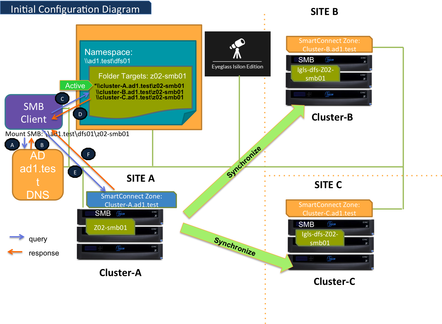
Initial Configuration
This diagram illustrates the initial configuration for a Multi-Site DFS Mode Failover setup. It provides an overview of how the namespace and failover targets are aligned across three sites:
- Site A: Serves as the source cluster, where the namespace and failover targets are defined.
- Site B and Site C: Configured as target clusters, with synchronization paths established from Site A.
The configuration ensures:
- Proper namespace management for failover targets.
- Synchronization between the source and target clusters.
Failover and Failback Paths
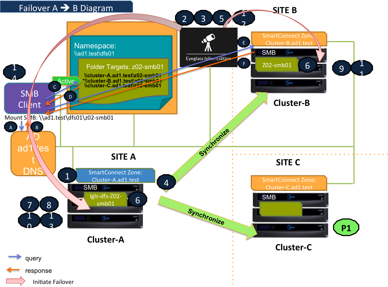
Failover Site A to Site B
The diagram below demonstrates the workflow for a Multi-Site DFS Mode Failover from Site A (Source) to Site B (Target #1).
To initiate this failover, ensure that all prerequisites, including the preparation step, are completed. Detailed procedural steps can be found in the Failover Steps section.
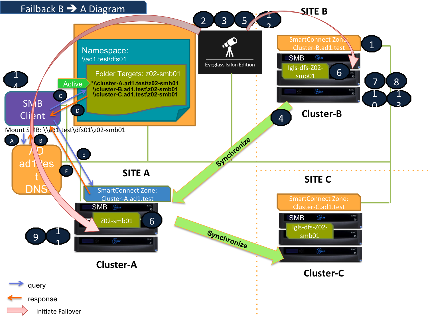
Failback Site B to Site A
The following diagram illustrates the workflow for a Multi-Site DFS Mode Failback from Site B (Target #1) to Site A (Source). This process restores operations to the original site while maintaining client access without requiring DNS or SPN changes.
Detailed procedural steps can be found in the Failback Steps section.
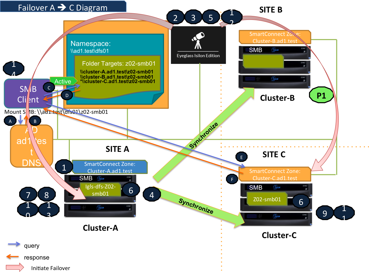
Failover Site A to Site C
The diagram below demonstrates the workflow for a Multi-Site DFS Mode Failover from Site A (Source) to Site C (Target #2). This failover process ensures seamless client redirection to the correct target site while keeping namespace and failover targets intact.
For detailed steps on initiating this failover, refer to the Failover Steps section.
Failback Site C to Site A
This diagram shows the workflow for a Multi-Site DFS Mode Failback from Site C (Target #2) to Site A (Source). It restores operations to the source site with automatic client redirection and no DNS or SPN updates required.
For detailed instructions, refer to the Failback Steps section.
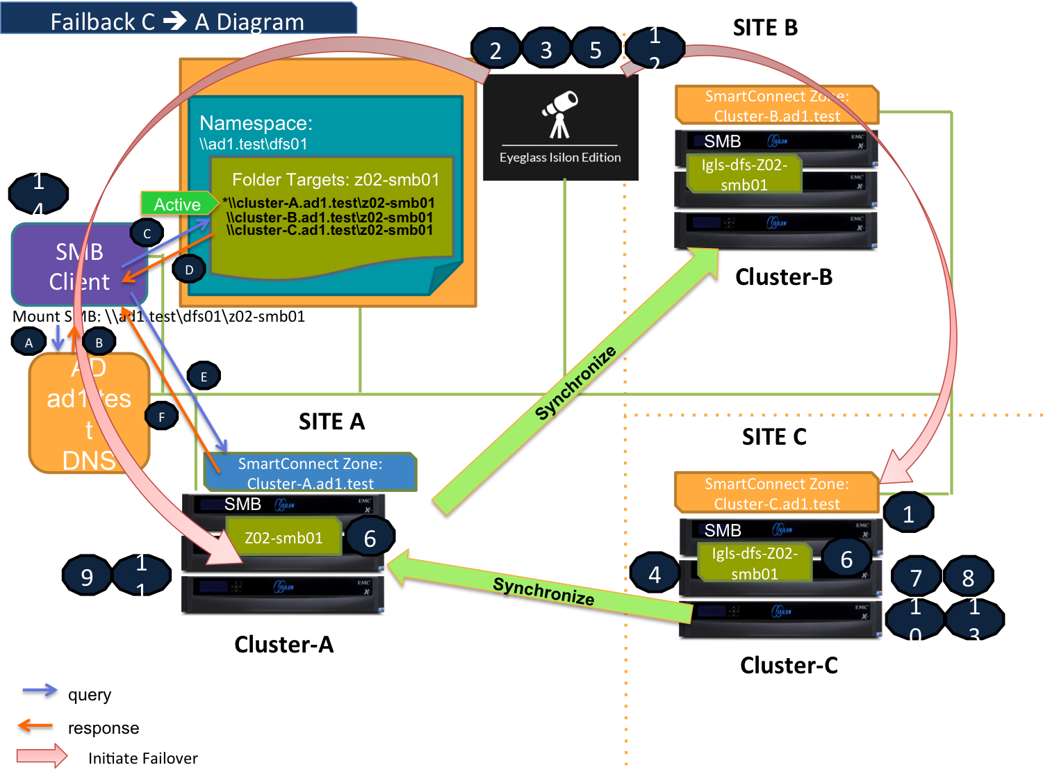
Failover and Failback Steps
Failover Steps
- Ensure there is no live access to data.
- Begin the failover process.
- Perform validation checks to confirm system readiness.
- Synchronize data between the source and target clusters.
- Synchronize configuration settings, including shares, exports, and aliases.
- Rename shares as needed to align with failover requirements.
- Record the schedule for SyncIQ policies being failed over.
- Prevent SyncIQ policies being failed over from running.
- Provide write access to data on the target cluster.
- Disable SyncIQ on the source cluster and activate it on the target cluster.
- Set the proper SyncIQ schedule on the target cluster.
- Synchronize quotas across clusters.
- Remove quotas on directories targeted by SyncIQ (PowerScale best practice).
- Refresh SMB session to pick up DNS change:
-
SMB Client Behavior:
- The SMB client accesses a domain-based namespace (e.g.,
\\ad1.test\dfs01\v02-smb01). - The SMB client sends a query to the AD to discover a list of root targets for the namespace.
- The SMB client accesses a domain-based namespace (e.g.,
-
AD Controller Response:
- The AD Controller returns a list of root targets defined for the requested namespace.
-
SMB Client Selection:
- The SMB client selects the root target from the referral list.
- The SMB client sends a query to the root server for the requested target.
-
DFS Root Server:
- The DFS root server constructs a list of folder targets in the referral and sends it to the client.
-
Failover Scenarios:
-
Failover A to B:
- The SMB share(s) on Cluster-A are renamed (prefixed with
igls-dfs-) and marked inactive. - The SMB share(s) on Cluster-C are deleted.
- The active path is set to Cluster-B (renamed to the actual name).
- The DFS root server sends this referral information to the client.
- The SMB share(s) on Cluster-A are renamed (prefixed with
-
Failover A to C:
- The SMB share(s) on Cluster-A are renamed (prefixed with
igls-dfs-) and marked inactive. - The SMB share(s) on Cluster-B are deleted.
- The active path is set to Cluster-C (renamed to the actual name).
- The DFS root server sends this referral information to the client.
- The SMB share(s) on Cluster-A are renamed (prefixed with
-
-
Connection Establishment:
- The SMB client establishes a connection to the active target defined in the list.
- PowerScale Active Target responds to the SMB connection, ensuring continuity of service.
-
Failback Steps
- Ensure there is no live access to data.
- Begin failback process.
- Perform validation checks to confirm system readiness.
- Synchronize data between the source and target clusters.
- Synchronize configuration settings, including shares, exports, and aliases.
- Rename shares as needed to align with failback requirements.
- Record the schedule for SyncIQ policies being failed back.
- Prevent SyncIQ policies being failed back from running.
- Provide write access to data on the target cluster.
- Disable SyncIQ on the source cluster and activate it on the target cluster.
- Set the proper SyncIQ schedule on the target cluster.
- Synchronize quotas across clusters.
- Remove quotas on directories targeted by SyncIQ (PowerScale best practice).
- Refresh SMB session to pick up DNS change:
-
SMB Client Behavior:
- The SMB client accesses a domain-based namespace (e.g.,
\\ad1.test\dfs01\v02-smb01). - The SMB client sends a query to the AD to discover a list of root targets for the namespace.
- The SMB client accesses a domain-based namespace (e.g.,
-
AD Controller Response:
- The AD Controller returns a list of root targets defined for the requested namespace.
-
SMB Client Selection:
- The SMB client selects the root target from the referral list.
- The SMB client sends a query to the root server for the requested target.
-
DFS Root Server:
- The DFS root server constructs a list of folder targets in the referral and sends it to the client.
-
Failback Scenarios:
-
Failback B to A:
- The SMB share(s) on Cluster-B are renamed (prefixed with
igls-dfs-) and marked inactive. - The SMB share(s) on Cluster-C are not active (renamed with the
igls-dfs-prefix). - The active path is set to Cluster-A (renamed to the actual name).
- The DFS root server sends this referral information to the client.
- The SMB share(s) on Cluster-B are renamed (prefixed with
-
Failback C to A:
- The SMB share(s) on Cluster-C are renamed (prefixed with
igls-dfs-) and marked inactive. - The SMB share(s) on Cluster-B are not active (renamed with the
igls-dfs-prefix). - The active path is to Cluster-A (renamed to the actual name).
- The DFS root server sends this referral information to the client.
- The SMB share(s) on Cluster-C are renamed (prefixed with
-
-
Connection Establishment:
- The SMB client establishes a connection to the active target defined in the list.
- PowerScale Active Target responds to the SMB connection, ensuring continuity of service.
-
Prerequisites
Referrals
Configure the DFS Target Folder to have 3 referrals: Site A, Site B, and Site C.
For example, the DFS Target Folder is configured with the following referrals:
- Source (Site A):
\\cluster07-o2.ad1.test\v02-smb01 - Target#1 (Site B):
\\cluster08-o2.ad1.test\v02-smb01 - Target#2 (Site C):
\\cluster06-o2.ad1.test\v02-smb01
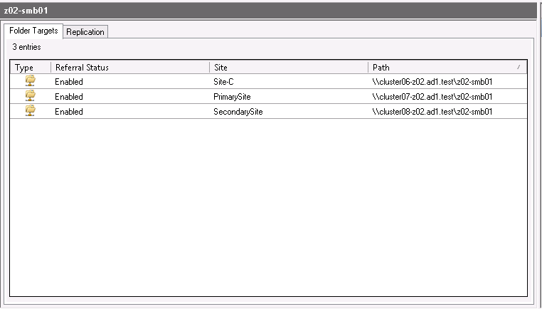
For this example, set the target priority referral ordering for the DFS Target Folders as follows:
- Enable override referral ordering for all clusters.
- Configure the following target priorities:
- Site A (Source Cluster): first among all targets.
- Site B (Target Cluster #1): last among all targets.
- Site C (Target Cluster #2): last among all targets.
DFS Readiness
This section explains the different states of DFS Readiness for this Multi-Site DFS Mode Failover / Failback example.
For the purpose of this example, we will refer to the following clusters:
- Site A (Primary / Source) as cluster07
- Site B (Secondary #1 / Target #1) as cluster08
- Site C (Secondary #2 / Target #2) as cluster 06
DFS Readiness - Initial Configuration, Before Failover
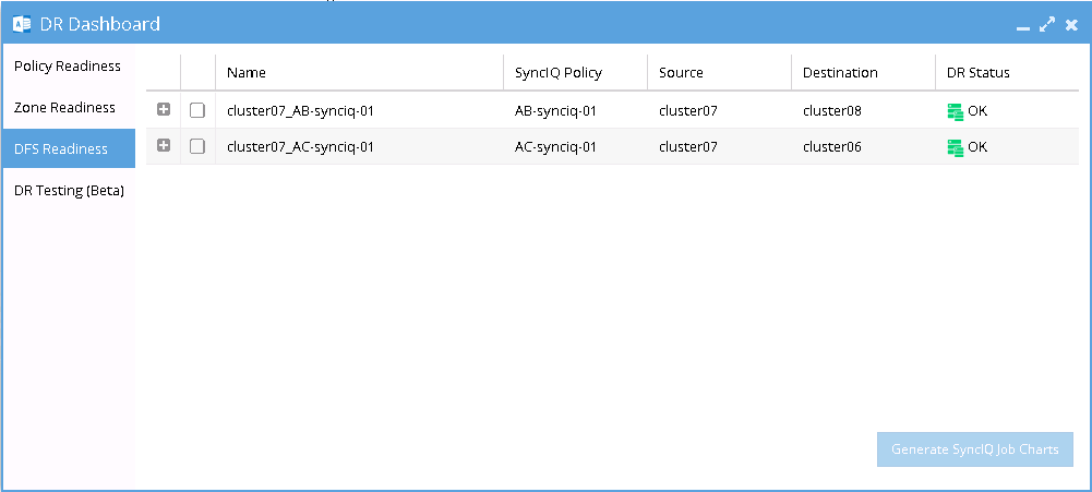
This represents the DFS readiness state for the initial configuration or pre-failover phase. The following image shows both source-target pairs (A-B and A-C) displayed in the DR Dashboard’s DFS readiness window.
The readiness status indicates that a DFS Mode failover can be initiated to any target cluster with a Green "OK" status or a "Warning" status.
DFS Readiness - Before Failback B to A
This DFS Readiness window shows the state before Failback from B to A
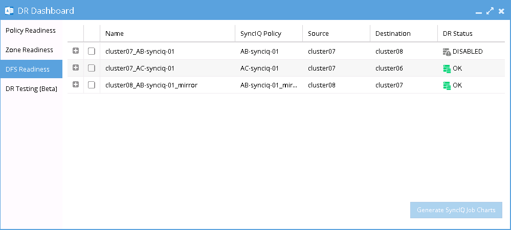
As shown in the DR Readiness Dashboard, both the AB Mirror Policy and AC Policy have a DR Status of "OK." During failback from B to A, it is critical to carefully select Cluster B as the source. Do not select Cluster A as the source, as this will trigger a failover from A to C instead.
DFS Readiness - Before Failback C to A
This DFS Readiness window shows the state before Failback from B to A
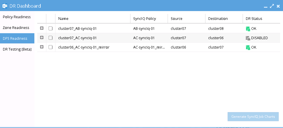
As shown in the DR Readiness Dashboard, both the AC Mirror Policy and AB Policy have a DR Status of "OK." During failback from C to A, it is critical to carefully select Cluster C as the source. Do not select Cluster A as the source, as this will trigger a failover from A to B instead.
Share Names and DFS Paths
Based on the above example, the following tables describe the SMB Share Names and DFS Paths for various states:
Initial Configuration, Before Failover
After Failover, After Failback
Configuration Details for DFS Multi-Site
Mirror Policy Prerequisites
Before Failover A to B
Delete any SyncIQ Mirror Policies from Site C to Site A to prevent overlaps that may cause failover failures.
Before Failover A to C
Similarly, delete any SyncIQ Mirror Policies from Site B to Site A.
DFS Mode Failover and Failback Procedures
DFS Mode Failover from A to B Procedure
-
Check for Mirror Policies:
Before initiating the Eyeglass DFS Mode Failover from A to B, ensure there are no existing SyncIQ Mirror Policies from Site C to Site A.
- Overlapping Mirror Target Paths can create conflicts, making Mirror Policies from B to A un-runnable and causing the Eyeglass Failover Job to fail.
- Delete any conflicting Mirror Policies before proceeding.
-
Run Domain Mark Job:
Execute a domain mark job on each SyncIQ policy on Cluster A.
- This is a required step to create domain marks used during the failover process.
- Best practice: Run the domain mark job before failover to ensure the resync prep step is completed quickly.
importantWhile the domain mark job is running, do not initiate a failover from A to C.
-
Select the Correct Target Cluster:
In the DR Assistant Wizard, carefully select the correct target cluster for the failover (in this case, A to B).
- Choose the appropriate zone for failover based on the source-target pairs, such as
cluster20(source) tocluster21(target).
- Choose the appropriate zone for failover based on the source-target pairs, such as
-
Review the Validation Screen:
The next screen in the DR Assistant Wizard will display a warning to highlight that only the selected Access Zone will failover (A to B).
- Other policies on the same Access Zone (e.g., A to C) will not be impacted during this failover.
-
Initiate the Failover:
Proceed with the failover operation as per normal. Refer to the Eyeglass DFS Mode Failover Guide for details.
DFS Mode Failback from B to A Procedure
Perform the Eyeglass DFS Mode Failback as per normal using the following steps:
-
In the DR Assistant Wizard, ensure you select the correct source cluster (Cluster B:
cluster08).- At this stage (after Failover A to B and before Failback B to A), selecting the wrong source cluster (e.g., Cluster A:
cluster07) will initiate a Failover from A to C instead.
importantThe above step must be completed before initiating A to C failover, as the domain mark will be deleted on Cluster A once this step is done.
- At this stage (after Failover A to B and before Failback B to A), selecting the wrong source cluster (e.g., Cluster A:
-
Run a domain mark job on each SyncIQ policy on Cluster A.
- This step is required to create domain marks used during the failback process.
- Best practice: Run the domain mark job before failback to ensure the resync prep step is completed quickly.
- During the domain mark job, do not initiate a failover from A to C.
- Monitor progress from the PowerScale Cluster jobs UI.
-
Select the AB mirror policy to failback.
- The next screen will validate whether the failback configuration is correct.
-
Proceed with the DFS Mode Failback.
- Refer to the Eyeglass DFS Mode Failover Guide for further details.
DFS Mode Failover from A to C Procedure
Perform the Eyeglass DFS Mode Failover from A to C as per normal using the following steps:
-
Check for Mirror Policies:
Ensure there are no existing SyncIQ Mirror Policies from Site B to Site A.
- Overlapping Mirror Target Paths can create conflicts, making Mirror Policies from C to A un-runnable and causing the failover to fail.
- Delete any conflicting Mirror Policies before proceeding.
-
Run Domain Mark Job:
Execute a domain mark job on each SyncIQ policy on Cluster A.
- This step is required to create domain marks used during the failover process.
- Best practice: Run the domain mark job before failover to ensure the resync prep step is completed quickly.
- Monitor progress from the PowerScale Cluster jobs UI.
importantDuring the domain mark job, do not initiate a failover from A to B.
-
Select the Correct Target Cluster:
In the DR Assistant Wizard, carefully select the correct target cluster for the failover (in this case, A to C).
- Choose the appropriate zone for failover based on the source-target pairs, such as
cluster20(source) tocluster31(target).
- Choose the appropriate zone for failover based on the source-target pairs, such as
-
Review the Validation Screen:
The next screen in the DR Assistant Wizard will validate whether the failover configuration is correct.
-
Proceed with the DFS Mode Failover:
Complete the failover operation. Refer to the Eyeglass DFS Mode Failover Guide for further details.
DFS Mode Failback from C to A Procedure
Perform the Eyeglass DFS Mode Failback from C to A as per normal using the following steps:
-
In the DR Assistant Wizard, ensure you select the correct source cluster (Cluster C:
cluster06).- At this stage (after Failover A to C and before Failback C to A), selecting the wrong source cluster (e.g., Cluster A:
cluster07) will initiate a Failover from A to B instead.
importantThe above step must be completed before initiating A to B failover, as the domain mark will be deleted on Cluster A once this step is done.
- At this stage (after Failover A to C and before Failback C to A), selecting the wrong source cluster (e.g., Cluster A:
-
Run a domain mark job on each SyncIQ policy on Cluster A.
- This step is required to create domain marks used during the failback process.
- Best practice: Run the domain mark job before failback to ensure the resync prep step is completed quickly.
- During the domain mark job, do not initiate a failover from A to B.
- Monitor progress from the PowerScale Cluster jobs UI.
-
Select the AC mirror policy to failback.
- The next screen will validate whether the failback configuration is correct.
-
Proceed with the DFS Mode Failback.
- Refer to the Eyeglass DFS Mode Failover Guide for further details.

